They can be formally confirmed with truth tables, but also understood intuitively. We know that \(A\) and \(B\) must both be true in order for \(A \cdot B\) to be true. If either \(A\) or \(B\) is false, therefore, \(A \cdot B\) will be false. Translated into algebra, we have the first rule, \(\overline{A \cdot B} = \overline{A} + \overline{B}\text{.}\) For the second rule, if both \(A\) and \(B\) are false, then \(A+B\) will be false. Translating into algebra, we have \(\overline{A + B} = \overline{A} \cdot \overline{B}\text{.}\)
Checkpoint3.4.1.
Confirm DeMorgan’s rules with a truth table
Solution.
\(A\)
\(B\)
\(\overline{AB}\)
\(\overline{A+B}\)
0
0
1
1
0
1
1
0
1
0
1
0
1
1
0
0
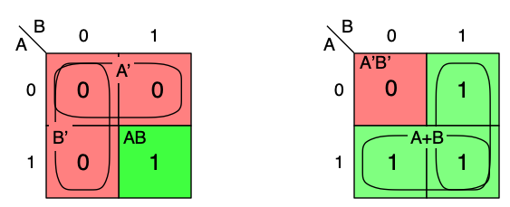
DeMorgan’s rules can also be visualized on a Karnaugh map, Figure 3.4.2.
Figure3.4.2.Karnaugh maps illustrating DeMorgan’s rules. (Left:) The red cells, where \(AB\) is FALSE, are covered by \(A' + B'\text{.}\) (Right:) The red cell, where \(A+B\) is FALSE, is \(A'B'\text{.}\)
Checkpoint3.4.3.
DeMorgan’s rules apply to more than two variables. Confirm, by Boolean algebra, that they work for three or more variables:
Here is the algebraic proof for the first rule, with three variables. Proof for the second rule is similar.
\begin{align*}
(A \cdot B \cdot C)' \amp= ( (A \cdot B) \cdot C )' = (A \cdot B)' + C'\\
\amp= A ' + B' + C'
\end{align*}
Once you see how it’s done for three variables, four or more follow the same pattern.
DeMorgan equivalent gates.
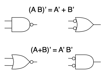
DeMorgan’s rules give a valuable interpretation of NAND and NOR gates, Figure 3.4.4. The bubble at the output of a NOT gate indicates logical inversion. A bubble may also be placed on an AND or OR gate to invert an input or output. Thus, a NAND gate is an AND gate with a bubble on the output, and a NOR gate is an OR gate with a bubble on the output.
Carrying the "bubble = NOT" symbolism farther, the expression \(A' + B'\) represents an OR gate with inverting bubbles on its inputs. DeMorgan’s rule, \((AB)' = A' + B'\text{,}\) says that this is equivalent to a NAND gate. We say that the AND with bubbled output and the OR with bubbled inputs are DeMorgan equivalent symbols for the NAND function. In the same way, the other DeMorgan’s rule, \((A+B)' = A' B'\text{,}\) says that the OR with bubbled output and the AND with bubbled inputs are DeMorgan equivalents for the NOR function.
Figure3.4.4.DeMorgan equivalent gate symbols. (Top:) By DeMorgan’s rule, \((A \cdot B)' = A' + B'\text{,}\) an AND gate with an output bubble is equivalent to an OR gate with input bubbles. (Bottom:) By DeMorgan’s rule, \((A+B)' = A' \cdot B'\text{,}\) an OR gate with an output bubble is equivalent to an AND gate with input bubbles.
Sum of products.
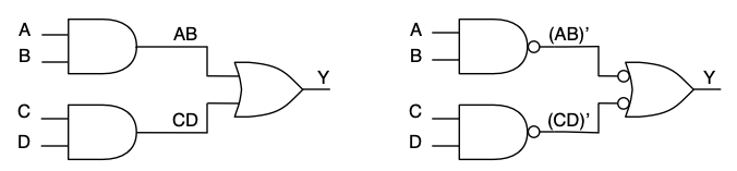
The DeMorgan equivalent representations of NAND and NOR enable a sum of products, \(Y = AB + CD\text{,}\) to be implemented solely with NAND gates, Figure 3.4.5. In the figure, the sum of products \(Y = AB + CD\) is initially implemented with two AND gates and one OR gate. The logic is unaffected by placing an inverting bubble at the end of each of the wires connecting the AND gates to the OR gate. The inversion at the output of the AND is undone by the inversion at the input of the OR. The output bubble converts the two ANDs to NANDs. Also, recognize that the OR with bubbled inputs is the DeMorgan equivalent symbol for a NAND.
Figure3.4.5.Using DeMorgan’s rule, \((A \cdot B)' = A' + B'\text{,}\) to implement a sum-of-products with NAND gates only. (Left:) A sum of products, \(Y = AB+CD\text{,}\) implemented with two AND gates and one OR gate. (Right:) Placing inverting bubbles at the outputs of the AND gates and the inputs of the OR gate change all three gates to NANDs, but does not change the logic.
What difference does this make? Two things: First, the circuit is constructed from only one kind of circuit, NAND, rather than two, AND and OR. This simplifies the layout of the circuit. Second, we have seen that a two-input NAND gate requires only four transistors, whereas the two-input AND and OR each require six (Section 2.4). The transistor count is reduced from eighteen to twelve, a signficant reduction in complexity and area.
When we first met the CMOS gate circuits in Section 2.4, it seemed awkward for the simplest gate circuits to be NAND and NOR. Now, thanks to DeMorgan’s rules, we see that they are actually superior to AND and OR. Any logic equation can be implemented using only NAND gates by first converting it to a sum of products. If it is necessary to invert a signal, e.g., \(y = A'B + AC\text{,}\) a NOT gate may be used.
Checkpoint3.4.6.
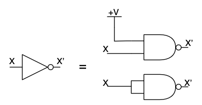
In a pinch, a NOT gate may also be replaced by a NAND. Show that both of the circuits below are equivalent to a NOT gate.
Solution.
In the upper circuit, \(X \cdot 1 = X\) (identity), therefore \(\overline{X \cdot 1} = \overline{X}\text{.}\) In the lower circuit, \(X \cdot X = X\) (idempotency), therefore \(\overline{X \cdot X} = \overline{X}\text{.}\)
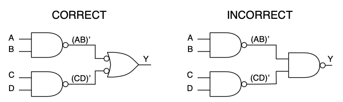
A final note about writing a sum of products using NAND gates. Using the DeMorgan equivalents, you can see that the circuit is a sum of products, and that the bubbles at the ends of the wires "cancel". Beginners will often convert the OR with bubbled inputs back to the other form, the AND with bubbled output, resulting in the circuit shown in Figure 3.4.7 This does not affect the underlying transistor circuit, but the diagram no longer visually communicates that the circuit is a sum of products. Don’t do this.
Figure3.4.7.The right way and wrong way to write a sum of products using NAND gates. (Left:) The DeMorgan equivalent symbols visually communicate that the circuit is a sum of products. This is the correct way to draw the circuit. (Right:) Replacing the final gate with the other DeMorgan form does not change the underlying circuit, but it obscures the meaning of the logic diagram.
Checkpoint3.4.8.
Draw the logic diagram for \(y = A'B + AC\text{,}\) using three NAND gates (with correct DeMorgan symbols) and a NOT gate.
Solution.
Checkpoint3.4.9.
Redraw the simplified two-bit \(x > y\) equation, Checkpoint 3.3.8, using NAND gates only (with correct DeMorgan symbols), and NOT gates, as needed.