
Based on your prior experience with other programming languages, what observations do you have about the architecture block in Listing 5.3.1? What questions do you have?
Section 5.3 Internal logic (architecture block)
Every VHDL model has an entity block that defines its interface to the outside world. This is analogous to a function prototype in a traditional programming language like C or Java. The entity declares the inputs and outputs, but says nothing about how the system actually processes the inputs to produce the outputs. The internal functionality of the system is described by the system’s architecture block. Because the architecture is where the actual work gets done, it is more complex than the entity block. However, we will see that VHDL is a highly structured and stylized language, almost template-like. It will not be difficult to write architectures for simple systems, and the architectures for more complex systems follow the same patterns.
Before moving ahead, you may want to watch this video (up to time 5:18), which reviews the entity block and gives a preview of the architecture block.
As a working example, let’s consider the two-input multiplexer, Checkpoint 1.4.4. It has two data inputs, \(A\) and \(B\text{,}\) select bit \(S\text{,}\) and output \(y\text{.}\) The logic equation is \(y = \overline{S} \cdot A + S \cdot B \text{.}\) The complete VHDL model for the multiplexer, based on the logic equation, is shown in Listing 5.3.1, below.
-- Two-input multiplexer model
   library IEEE;
   use IEEE.std_logic_1164.all;

   entity mux2to1 is
       port( A, B:  in  std_logic;     -- inputs
             S:     in  std_logic;     -- select bit
             y:     out std_logic );   -- output
   end mux2to1;

   architecture gatelevel of mux2to1 is
   begin
       y <= (not(S) and A) or (S and B);
   end gatelevel;
Checkpoint 5.3.2.
The listing includes a header line describing the model. Multiple header lines (they are just comments) are helpful for the reader, to provide information about the project, engineer, date created, revisions, etc. The next two lines, before the entity block, must appear in every VHDL model you write. They are library statements that, among other things, make the std_logic and std_logic_vector datatypes available for use. Next is the entity block; note here that the data inputs, \(A\) and \(B\text{,}\) are declared in the same line. Sometimes this is convenient, if the the ports are closely related in function.
The architecture block proper is set off by the line
architecture gatelevel of mux2to1 is. You can think of it as saying “this is a gate-level (logic equation) model for the mux2to1 entity”. The label gatelevel is purely descriptive, and can be any word you find useful, though only certain labels are commonly used in practice. The statements comprising the architecture are bracketed by begin ... end.The logic equation itself,
y <= (not(S) and A) or (S and B); looks much as it would in any computer language, with the particular note that the VHDL assignment operator is <=. (The plain = operator is reserved for testing equality, like == in C.) The assignment operator is usually read “gets”, e.g., y <= (not(S) and A) is read “y gets not S and A”.Now, to make a point, we’ll write the architecture again, making a literal translation of the logic diagram into multiple logic equations. This is not an efficient way to write the model for the multiplexer, but it provides a simple introduction to an important feature of VHDL models. The gate-level logic diagram is shown in Figure 5.3.3. The nets between the AND gate outputs and OR gate inputs are named asn and bs, denoting “a and not s” and “b and s”, respectively.
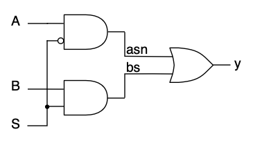
Logic diagram.
A VHDL model using these intermediate signals is shown in Listing 5.3.4. The key feature is the way the intermediate nets are declared and used:
- They are declared with the keyword
signal, in the location shown, within the architecture but before thebegin...endcontaining the logic itself. - Signals are local to the architecture and unknown to the entity and the outside world.
- Like ports, they are declared with a datatype (here,
std_logic). - Signals and ports may be mixed in a logic equation, as long as they are of the same type (which, for now, is easy).
-- Two-input multiplexer model, gate-by-gate
   library IEEE;
   use IEEE.std_logic_1164.all;

   entity mux2to1 is
       port( A, B:  in  std_logic;     -- inputs
             S:     in  std_logic;     -- select bit
             y:     out std_logic );   -- output
   end mux2to1;

   architecture gatelevel of mux2to1 is
       signal asn, bs: std_logic;      -- intermediate nets
   begin
       asn <= not(S) and A;
       bs <= S and B;
       y <= asn or bs;
   end gatelevel;
As with the first listing, the equations themselves look the way they would if they were written in a conventional computing language. The three statements would be executed in order, first computing the two intermediate values and then combining them to make the result. In VHDL, however, we are modeling hardware, and in an electronic circuit all the components are operating, simultaneously, all the time. VHDL captures this property of hardware with the idea of concurrency.
Unlike a conventional programming language, in VHDL these two arrangements of the equations are equivalent:
asn <= not(S) and A;
bs <= S and B;

y <= asn or bs;
y <= asn or bs;

asn <= not(S) and A;
bs <= S and B;
They both express the concurrent logic of the circuit diagram: two AND gates combining the inputs, and an OR gate combining the outputs of the AND gates. Concurrency is essential to the way that VHDL is able to model hardware. In the next chapter we will begin to see how it works.
Example 5.3.5.
Here is an example of using std_logic_vectors to simplify the entity and architecture. Recall the logic equations for the one-hot decoder, Checkpoint 1.4.3,
\begin{align*}
y_0 \amp= \overline{n_1} \cdot \overline{n_0} \\
y_1 \amp= \overline{n_1} \cdot n_0 \\
y_2 \amp= n_1 \cdot \overline{n_0} \\
y_3 \amp= n_1 \cdot n_0
\end{align*}
We could write the entity with two one-bit inputs and four one-bit outputs, but it will be more compact to use a two-bit std_logic_vector input and a four-bit std_logic_vector output. Try it yourself, then check the answer.
Hint.
Individual elements of a vector are referenced by their indices, e.g.,
y(0) is the least significant bit of the vector y declared as std_logic_vector(3 downto 0).Answer.
The VHDL model for this one-hot decoder is
-- Two-input one-hot decoder model, gate level
   library IEEE;
   use IEEE.std_logic_1164.all;

   entity decoder_onehot2 is
       port( n:  in  std_logic_vector(1 downto 0);     -- input
             y:  out std_logic_vector(3 downto 0) );   -- output
   end decoder_onehot;

   architecture gatelevel of decoder_onehot is
   begin
       y(0) <= not(n(1)) and not(n(0));
       y(1) <= not(n(1)) and n(0);
       y(2) <= n(1) and not(n(0));
       y(3) <= n(1) and n(0);
   end gatelevel;
Exercises Exercises
1. VHDL models.
Complete the VHDL models for these earlier examples. Use std_logic_vectors when appropriate.
- Two-bit odd number circuit, Checkpoint 1.4.2.
- Two-bit \(x \gt y\) circuit, Checkpoint 1.3.4.
- Priority encoder, Checkpoint 1.3.7.

