
Section 16.2 Multi-digit display
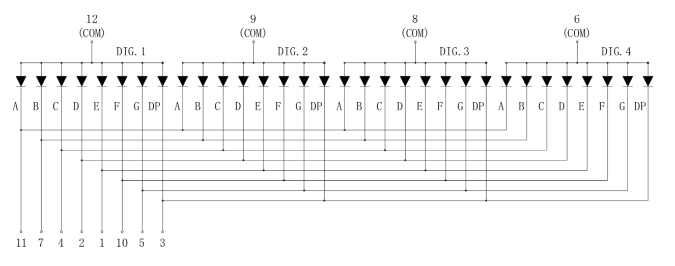
A single display has eight or nine terminals---seven segments, maybe a decimal point, and a common. The Basys3 board has a four-digit display, but each segment does not have its own terminal (which would use up 28 or 32 of the FPGA’s pins). Rather, the four digits are wired together as shown in Figure 16.2.1. Each digit has its own common anode terminal. The cathodes of the four A segments are wired together to a common "A" terminal. Likewise, the cathodes of the B segments are wired together to a common "B" terminal, and so forth. The C segment of Digit 2, say, is activated by pulling the Digit 2 anode terminal (pin 9) HIGH, and pulling the C segment terminal (pin 4) low.
The wiring of the display to the FPGA is shown in Figure 16.2.2. The cathode terminals are wired through 100-ohm current limiting resistors directly to pins on the FPGA (not shown). These wires are labeled CA-CG and DP. With the current-limiting resistor, the current draw of a segment is within the capacity of the FPGA’s output. The anode terminals (A1-A4), on the other hand, must be able to carry enough current for the entire digit, which is 8 times the current of a single segment. This is too much current for an FPGA pin to source directly, and so transistor drivers (Q1A, Q1B, Q2A, Q2B) with greater current-carrying capacity are used. The wires labeled AN0-AN3 are wired to the FPGA. When one of them, say AN0, is pulled LOW, its transistor is turned on, and current flows from the 3.3V power supply, denoted VCC3V3, into Pin 6, the digit’s common anode terminal (Digit 4, as it turns out; the labeling isn’t perfectly consistent).
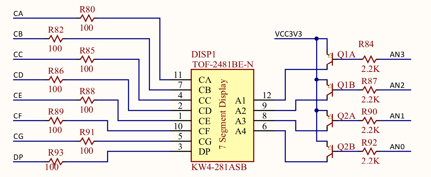
This explains how the display works, electrically. We will need some logic to display a four-digit number.

