
Fill in the algebraic steps leading to the voltage divider equations.
Section 2.2 Electric circuits
A complex electrical circuit may have several branches that the current can follow in its journey from positive to negative (Figure 2.2.1)
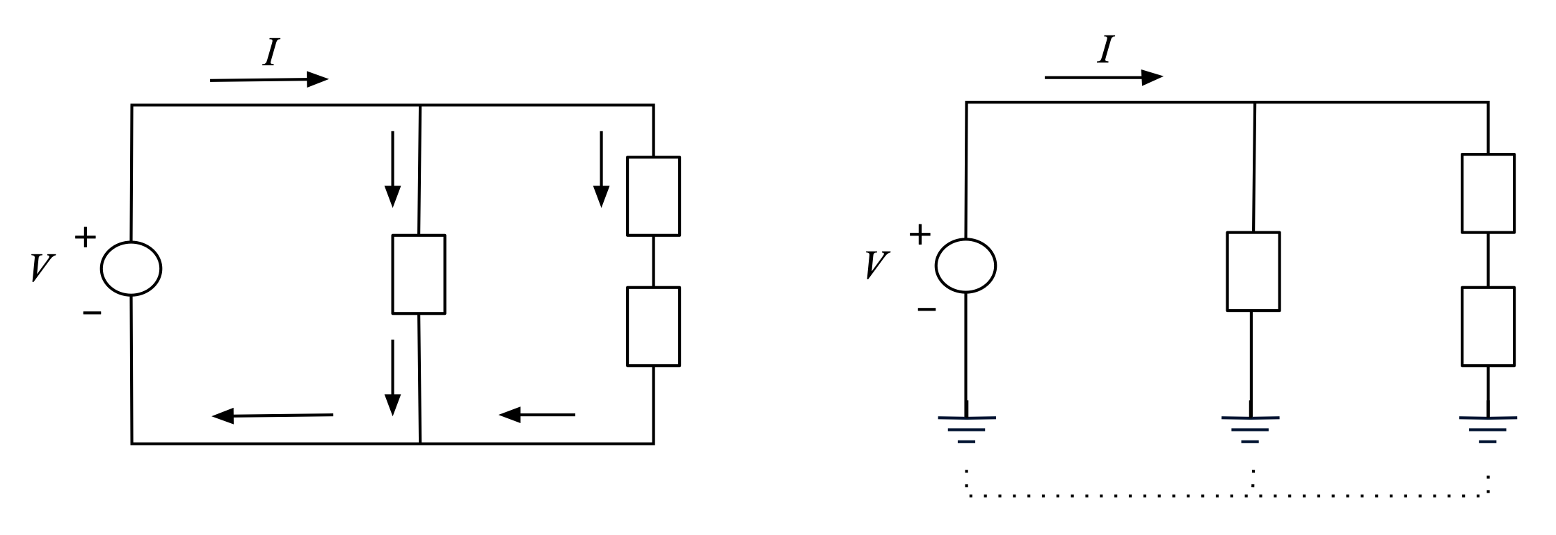
It is frequently convenient to abbreviate the common return path to the negative power supply terminal by drawing the "common" or "ground" symbol at the end of each branch and on the negative terminal, as shown in the figure. It is understood that there is a wire connecting all the ground terminals together. The ground symbolizes an actual earth connection in some electrical systems, but in digital electronics it is simply used to represent a common connection to the negative supply terminal.
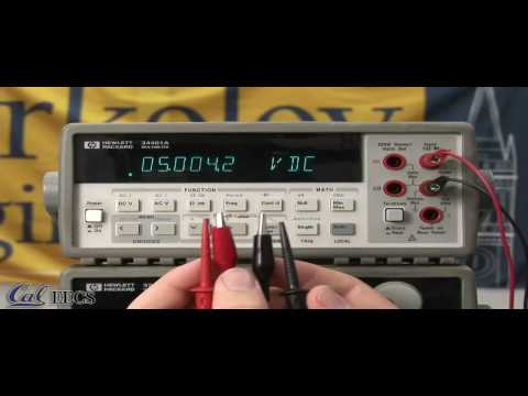
Voltage and current are measured in a circuit with a voltmeter and ammeter, respectively. The resistance of a component is measured with an ohmmeter, outside the circuit. (Do not try to measure resistance of a component in a circuit with an ohmmeter, especially if the circuit has power applied!) In the lab, these measurement functions are bundled into one instrument called a multimeter. Figure 2.2.2, below, illustrates how voltage, current, and resistance are directly measured with a multimeter.
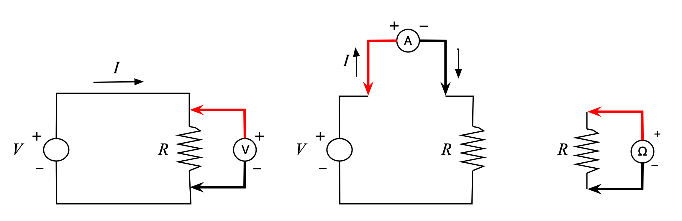
In addition to direct measurements, any of these three quantities can be indirectly measured using the other two, via Ohm’s law. Rather than breaking a circuit to insert an ammeter, for example, the voltage drop across a known resistor can be measured, and the current calculated from \(I=V/R\text{.}\)
Here is a video, from U.C. Berkeley, with more information about the multimeter.
Voltage divider.
Here is a simple circuit with two resistors, connected in series, called a voltage divider.
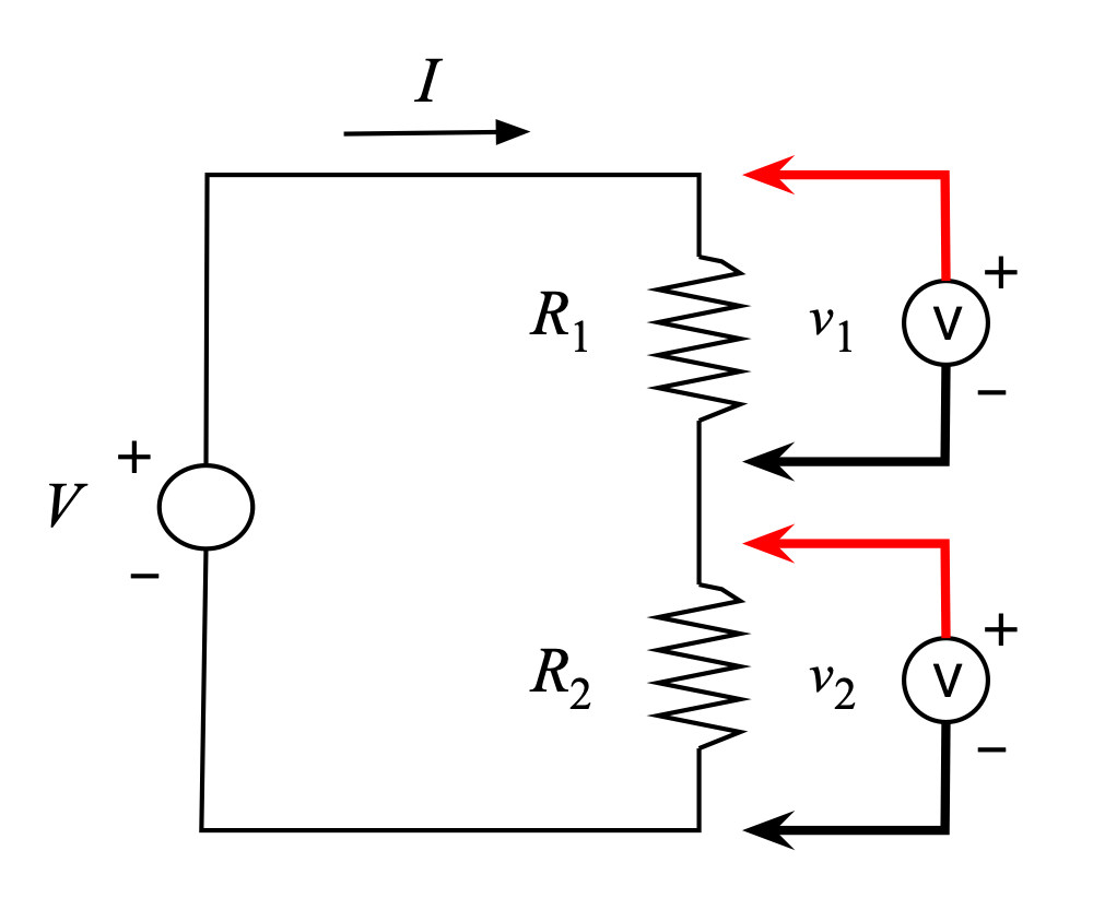
Before making measurements in the lab, let’s do a thought experiment using Ohm’s law. The current through resistor \(R_1\) is \(v_1/R_1\text{,}\) and the current through \(R_2\) is \(v_2/R_2\text{.}\) The same current passes through both resistors; the current flowing out of \(R_1\) is equal to the the current flowing into \(R_2\text{,}\) a consequence of the principle known as Kirchoff’s current law, so we have
\begin{gather*}
I = \frac{v_1}{R_1} = \frac{v_2}{R_2}
\end{gather*}
It is also true that \(V = v_1 + v_2\text{,}\) a consequence of the principle known as Kirchoff’s voltage law. We can combine these two expressions and obtain expressions for the voltage drops \(v_1\) and \(v_2\text{:}\)
\begin{align*}
v_1 \amp= \frac{R_1}{R_1 + R_2} V \\
v_2 \amp= \frac{R_2}{R_1 + R_2} V
\end{align*}
The circuit is called a voltage divider, because the supply voltage \(V\) is divided between the two resistors.
Checkpoint 2.2.4.
Checkpoint 2.2.5.
A voltage divider has two resistors, with \(R_1 \gt R_2\text{.}\) Which of the following statements is true?
- \(\displaystyle v_1 \gt v_2\)
- \(\displaystyle v_1 = v_2\)
- \(\displaystyle v_1 \lt v_2\)
Answer.
The larger resistor has the larger voltage drop. Hence, (1) is true.
Checkpoint 2.2.6.
You have a 5V supply and want to use a voltage divider to reduce the voltage to \(v_2 = 1\text{V}\text{.}\) What should the resistor ratio \(R_1/R_2\) be?
Solution.
Use the equation \(v_2 = \frac{R_2}{R_1 + R_2} V\text{.}\) Then,
\begin{align*}
\frac{R_1 + R_2}{R_2} = \frac{R_1}{R_2} + 1 \amp= \frac{V}{v_2}\\
\frac{R_1}{R_2} \amp= \frac{V}{v_2} - 1 = \frac{5}{1} - 1 = 4:1
\end{align*}
Checkpoint 2.2.7.
According to the voltage divider equations, what is the approximate value of \(v_2\) in the cases where \(R_1 \gg R_2\) (including \(R_2 = 0\)), on the one hand, and \(R_1 \ll R_2\) (including \(R_1 = 0\)), on the other hand?
Answer.
When \(R_1 \gg R_2\text{,}\)
\begin{align*}
v_2 \amp= \frac{R_2}{R_1 + R_2} V \approx \frac{R_2}{R_1} V \approx 0
\end{align*}
and when \(R_1 \ll R_2\text{,}\)
\begin{align*}
v_2 \amp= \frac{R_2}{R_1 + R_2} V \approx \frac{R_2}{R_2} V = V
\end{align*}
Experiments.
Here are two experiments you can do to practice making voltage measurements. You will need a breadboard, power supply (a battery will do), multimeter, and an assortment of resistors. You can use the multimeter to measure the resistor values, or learn to read the resistor color code.
1
www.digikey.com/en/resources/conversion-calculators/conversion-calculator-resistor-color-code-4-band-
Wire up the voltage divider circuit, Figure 2.2.3, with any two resistors. Measure the resistor voltages with the voltmeter leads attached in the normal way, according to the figure. Then reverse the voltmeter leads (red and black) and repeat the measurements. What do you observe?
\(v_1\) \(v_2\) Leads normal \(\qquad \qquad\) \(\qquad \qquad\) Leads reversed \(\qquad \qquad\) \(\qquad \qquad\) -
Wire up the voltage divider circuit and fill in this table for several resistor pairs. (Be sure to attach the voltmeter leads in the normal way, according to Figure 2.2.3). Using the voltage divider equations, predict the voltage drops, then confirm them with measurements.
Resistors Predicted Measured \(\qquad R_1 \qquad \) \(\qquad R_2 \qquad \) \(\qquad v_1 \qquad \) \(\qquad v_2 \qquad \) \(\qquad v_1 \qquad \) \(\qquad v_2 \qquad \) \(\) \(\) \(\) \(\) \(\) \(\)
Light emitting diodes.
When a circuit has something to say to you, it often turns on a light emitting diode (LED). An LED is an electronic device that emits light in response to the current flowing through it. A simple LED circuit is shown below. The resistor controls the amount of current flowing through the LED, and hence the brightness of the light.
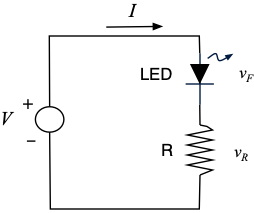
The terminals of the LED are called the anode (the triangle, in the symbol) and the cathode (the horizontal bar, in the symbol). The LED has three salient properties:
- Current only flows in one direction, from the anode to the cathode. The anode is connected toward the positive power supply, and the cathode toward the negative, or ground.
- Current will flow when the anode voltage (relative to ground) exceeds the cathode voltage (relative to ground) by an amount called the forward voltage. Once current is flowing, the voltage across the LED remains relatively constant over a wide range of currents (the LED does not obey Ohm’s law).
- The LED has a maximum allowed current. If this current is exceeded, the LED will overheat and burn out.
You can read more about LEDs in this tutorial from SparkFun Electronics.
2
learn.sparkfun.com/tutorials/light-emitting-diodes-ledsThe value of an LED’s forward voltage is given in its datasheet. Otherwise, you can measure it with a voltmeter in a test circuit. Once you know it, you can use Ohm’s law to calculate the resistor value needed to obtain a particular current. This is important, because operating an LED without a current-limiting resistor will likely result in burning it out. Here is how we derive an expression for \(R\text{:}\)
- Using Kirchoff’s voltage law, \(V = v_F + v_R\text{.}\)
- Using Ohm’s law, the voltage drop across the resistor is \(v_R = IR\text{.}\)
- Combine these two equations to solve for \(R\) in terms of the other parameters:\begin{align*} V \amp= v_F + IR\\ \implies \ R \amp= \frac{V - v_F}{I} \end{align*}
Example 2.2.9.
In Figure 2.2.8, suppose the LED’s forward voltage \(v_F\) can range from a minimum 3.0V to maximum 3.4V. The maximum allowed steady current is 20mA, and the suggested operating current is 16-18 mA (datasheet). The power supply voltage is \(V=5\text{V}\text{.}\)
3
cdn.sparkfun.com/datasheets/Components/LED/10mm%20green%20LED%20YSL-R1047G5D-D2-1.pngCalculate the resistor value required to limit the LED current to not exceed the 20mA maximum, for any forward voltage between 3.0V and 3.4V. This is called a worst-case design.
Solution.
Use the equation for \(R\text{,}\) with \(V=5\text{V}\text{,}\) \(v_F=3.0\text{V}\text{,}\) and \(I=20\text{mA}=0.02\text{A}\text{:}\)
\begin{gather*}
R = \frac{V - v_F}{I} = \frac{5 - 3}{0.02} = 100\Omega
\end{gather*}
Repeat with \(v_F = 3.4\text{V}\text{:}\)
\begin{gather*}
R = \frac{V - v_F}{I} = \frac{5 - 3.4}{0.02} = 80\Omega
\end{gather*}
Choose the larger of the two values to be safe.
Checkpoint 2.2.10.
Visit the SparkFun or Adafruit websites and look at their single LEDs, e.g.,
- SparkFun, 5mm green LED, also available red, blue, yellow
4
www.sparkfun.com/products/9592 - Adafruit, 5mm superbright red LED, also available green, blue, yellow
5
www.adafruit.com/product/297
and note any differences in forward voltage with color.
Experiment.
Here is an experiment you can do to become familiar with LEDs. You will need a breadboard, 5V power supply, LED, and three resistors spread between 100 and 800 ohms. Wire up the circuit in Figure 2.2.8. For each of your resistor values, measure \(v_F\) and \(v_R\text{,}\) calculate the current, and note the brightness in the table below:
| \(\qquad R \qquad \) | \(\qquad v_F \qquad \) | \(\qquad v_R \qquad \) | \(\qquad I \qquad \) | comment on brightness |
| \(\) | \(\) | \(\) | \(\) | |
| \(\) | ||||
| \(\) |
Safety note.
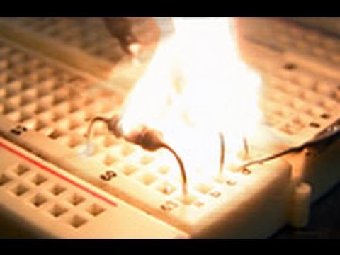
While the voltages and currents in digital circuits are usually low, there are situations that can result in damage to components and, more importantly, injury to you. It is a common joke that electronic devices run on magic smoke. If you ever let the magic smoke out of a device, it will stop working. What is not funny is that the release of smoke is usually preceded by serious overheating that can burn skin and, occasionally, an explosive release of flame and molten material.
Before you ever apply power to a circuit, check that you have correctly wired the power and ground pins of your integrated circuits. Wiring them backwards will almost always result in overheating and damage. Always make sure that your power supply is set to the correct voltage (usually, either 3.3V or 5V) with proper polarity (positive to the red wire / power pins, negative to the black wire / ground pins). Never run an LED without a current limiting resistor. If you notice a "hot" smell, turn the power off immediately and be very careful about touching anything in your circuit until it has had a chance to cool. Then check your wiring again.
Here is a brief video with some spectacular examples of overheated electronic components.
We now have enough of the basic principles of electricity to start seeing how logic gates work on the inside.

