Another important application mixing asynchronous and synchronous functionality is a counter that asserts an output when its terminal count is reached. We’ll approach the design in two stages: first, modeling a counter with an arbitrary maximum count, and second, asserting a terminal count signal when that maximum is reached.
Counter with arbitrary maximum count.
Recall the basic four-bit counter model (see Listing 8.3.4).
library ieee;
use ieee.std_logic_1164.all;
use ieee.numeric_std.all;

entity counter4 is
   port( clk:    in  std_logic;
         X:      out std_logic_vector(3 downto 0) );
end counter4;

architecture behavior of counter4 is
   signal uX:    unsigned(3 downto 0);

begin
ctr8: process(clk)
   begin
      if rising_edge(clk) then
        uX <= uX + 1;
      end if;
   end process ctr4;

   X <= std_logic_vector(uX);
end behavior;
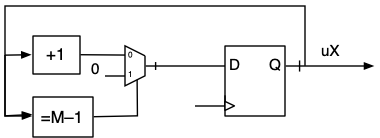
This counter rolls over to 0 when it reaches 15. A more flexible counter can be designed with an arbitrary upper limit, \(M-1\text{.}\) To do this, we have to detect that the count is \(M-1\text{,}\) with a comparator, and then use that signal to clear (load zeros into) the counter. A block diagram looks like this:
The comparator output is the select bit for a multiplexer, choosing between the incremented count and zero. The multiplexer and the register are combined into a single process in this model (for counting from 0 to 9, also known as a decade counter):
architecture behavior of counter4 is
   constant M: integer := 10;          -- 1
   signal uX:  unsigned(3 downto 0);

begin
ctr4: process(clk)
   begin
      if rising_edge(clk) then
         if uX = M-1 then              -- 2
            uX <= "0000";
         else
            uX <= uX + 1;              -- 3
         end if;
      end if;
   end process ctr4;

   X <= std_logic_vector(uX);
end behavior;
Listing9.2.1.VHDL model for a decade (0-9) counter. Comments are keyed to explanations in the text.
New features in this model are:
The upper limit of the counter is defined via a named integer constant, following good programming practice. M is 10, the number of counter states (0, 1, ..., 9).
The numeric_std library includes all the arithmetic comparison operators, such as = [6]. A signal of unsigned (or signed) type may be compared with a constant of integer type. If the count is seen to be \(M-1\text{,}\) then it is reset to 0.
Otherwise, the count is incremented.
Asserting the terminal count signal.
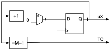
Next, we need to assert the terminal count signal, TC, when the count equals \(M-1\text{.}\) We already have a comparator in the logic diagram, above, so we just need to assign the comparator’s output to TC.
Figure9.2.2.Logic diagram of a counter with terminal count output.
One way model this in VHDL is to put the counter update logic in one synchronous process, and the comparator in a concurrent asynchronous process. The complete VHDL model is shown below.
ctr4: process(clk)
begin
   if rising_edge(clk) then
      if iTC = '1' then
         uX <= "0000";
      else
         uX <= uX + 1;
      end if;
  end if;
end process ctr4;

TCcomp: process(uX)
begin
  if uX = M-1 then
      iTC <= '1';
  else
      iTC <= '0';
  end if;
end process TCcomp;
This is logically and syntactically correct, and will produce the desired behavior in simulation. Its disadvantage, stylistically, is that the separation of the counter into two processes makes the code less readable. The model is made more compact and readable if all the counter’s functionality is packed into a single process, like this:
entity counter4 is
      port( clk:    in  std_logic;
            X:      out std_logic_vector(3 downto 0);
            TC:     out std_logic; );
   end counter4;

   architecture behavior of counter4 is
      constant M:   integer := 10;     -- decade counter
      signal uX:    unsigned(3 downto 0) := "0000";
      signal iTC:   std_logic := '0';  -- 1

   begin
      ctr4: process(clk, uX)           -- 2,5,8
      begin
      -- Synchronous count update
         if rising_edge(clk) then      -- 3,6,9
            if iTC = '1' then
               uX <= "0000";
            else
               uX <= uX + 1;
            end if;
        end if;

       -- Asynchronous TC comparator
        if uX = M-1 then               -- 4,7
            iTC <= '1';
        else
            iTC <= '0';
        end if;
      end process ctr4;

      X <= std_logic_vector(uX);
      TC <= iTC;
   end behavior;
Listing9.2.3.VHDL model of a decade counter with terminal count output. See Figure 9.2.4 for timing diagram. Comments are keyed to notes in the text.
Follow the steps in the execution of the process and see how the synchronous and asynchronous parts mesh. Assume an initial count of 8.
Declare internal signals, uX and iTC, that may be read and written. The ouptut ports X and TC may only be written, not read.
A rising clock edge causes the process to activate.
Because uX is 8, (internal) terminal count iTC was previously set to 0, so the counter will update from 8 to 9.
The current value of the count (8) does not yet equal 9, so iTC will be ’0’.
The process suspends with uX=9 and iTC = ’0’. These values are mapped to the output ports X and TC. The change in uX from 8 to 9 makes an event on uX and reactivates the process (uX is on the sensitivity list in addition to clk).
The synchronous part does not evaluate, because there is no clock edge.
The current value of the count (9) equals 9, and iTC will be asserted when the process suspends.
The next rising edge will activate the process.
Because iTC is now 1, the counter will reset when the process suspends.
Simulation, Figure 9.2.4, shows that the counter resets and the terminal count signal is asserted at the appropriate time.
Figure9.2.4.Timing diagram for counter with terminal count (TC) output, produced by simulation of the VHDL model, Listing 9.2.3. The counter resets and the TC output is asserted when the count is 9.
ExercisesExercises
1.Safe decade counter.
The decade counter design, Listing 9.2.1, has one vulnerability. If a glitch were to cause it to skip to a value greater than 9, it would keep counting until it naturally rolled over at 15. Modify the design to avoid this problem.
Answer.
Change the comparator from \(=\) to \(\ge\text{:}\)
ctr4: process(clk)
   begin
      if rising_edge(clk) then
         if uX >= M-1 then
            uX <= "0000";      -- reset
         else
            uX <= uX + 1;      -- increment
         end if;
   end process ctr4;
2.An incorrectly modeled terminal count.
A common mistake is to write the VHDL model for a counter with terminal count output like this:
ctr4: process(clk)
begin
   if rising_edge(clk) then
      if uX = M-1 then
         uX <= "0000";
         TC <= '1';
      else
         uX <= uX + 1;
         TC <= '0';
      end if;
   end if;
end process ctr4;
Simulate this design and observe that the TC signal is asserted at the wrong time. Reverse engineer the VHDL model to a logic diagram, and use it to explain what went wrong.
Answer.
The simulation is:
The TC signal is asserted when the count is 0, one clock cycle delayed. The logic diagram represented by this model is:
In the VHDL model, the TC signal is updated on the rising edge, so it is stored in a flip-flop. When the count, uX, is 9, the TC signal is not set until the next clock edge, at which time uX is also set to 0. The extra flip-flop following the comparator is introducing the erroneous delay. This is a very common design pitfall.