Section9.1Flip-flop model with asynchronous controls
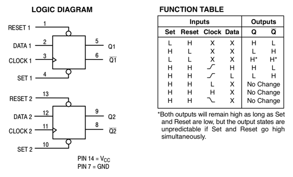
Some classic discrete integrated circuits containing flip-flops have the ability to set and clear the state at any time, independent of the clock. A simple example, the HC74A dual flip-flop [9], is shown below.
Figure9.1.1.Logic diagram (left) and function (truth) table (right) for the HC74A dual D flip-flop with asynchronous set and clear [9].
Each flip-flop has its own clock, data, set and reset inputs. SET and RESET are low-true (shown by the bubbles). On the truth table, SET and RESET inputs are both HIGH, the flip-flop operates in the usual edge-triggered mode. When SET is HIGH and RESET is LOW, the output, Q, immediately (after a small propagation delay) becomes LOW (0). The complementary output, Q’, becomes HIGH (1). These transitions, in response to the SET and RESET inputs without regard to the clock, are asynchronous. Similarly, when SET is LOW and RESET is HIGH, Q immediately becomes HIGH (1), and Q’ becomes LOW (0), asynchronously.
The HC74A has an additional, problematic “feature”. If SET and RESET are both LOW (that is, TRUE), the circuit enters a paradoxical state where Q and Q’ are simulaneously HIGH. After this, when one of the inputs goes HIGH, the output resolves to one of the other defined outcomes. In the very rare and undesirable case of SET and RESET becoming HIGH or LOW simultaneously, the circuit’s behavior is said to be unpredictable. This strange situation must be avoided, by using only one of the control inputs and tying the other HIGH to disable it, or by tying both inputs HIGH and using the flip-flop as a purely synchronous device. There are good applications of asynchronous inputs, but in this course you are instructed not to use them.
That said, here is how the HC74A would be modeled...almost. Rather than trying to accurately account for the SET=RESET=LOW situation, this model gives SET priority over RESET. Additionally, according to the truth table, SET and RESET have priority over the clock.
-- clock1, data1, set1, reset1, Q1, Qbar1 are std_logic
HC74A_1: process(clk, set1, reset1)
   begin
      if set1='0' then               -- low-true
         Q1 <= '1';
         Qbar1 <= '0';
      elsif reset1='0' then          -- low-true
         Q1 <= '0';
         Qbar1 <= '1';
      elsif rising_edge(clock1) then   -- Asynch inputs have priority over synch
         Q1 <= data1;
         Qbar1 <= not(data1);
      end if;
   end process HC74A_1;
Listing9.1.2.VHDL model of one half of the MC74HC74A dual flip-flop [9].
ExercisesExercises
1.Simulation: HC74A.
Write a testbench for the HC74A model, Listing 9.1.2, that verifies all the functions specified in the truth table, Figure 9.1.1. Then carry out a simulation.