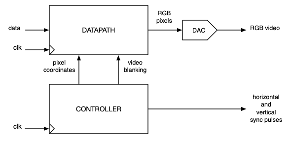
A VGA display interface must do two things: Produce the stream of pixels from the data to be displayed, and generate the horizontal and vertical sync pulses that synchronize the monitor with the pixel stream Figure 20.3.1. We can designate the part that produces the pixel stream as the datapath for the interface, and the part that makes the sync pulses the controller. We will begin with the controller in this section and then present a couple of options for datapath design in the next section.
Figure20.3.1.Block diagram of VGA interface. The controller generates horizontal and vertical sync pulses to synchronize the monitor. The datapath uses pixel coordinates and blanking signals from the controller to produce the stream of red, green, and blue pixel (RGB) pixel values, which are converted to three analog red, green, and blue video signals by digital-to-analog converters (DACs).
The timing of the blanking and sync signals was shown in Figure 20.2.3. The same information, in a tabular format, is shown in Figure 20.3.2.
Horizontal (pixels)
Vertical (lines)
Active area
640
480
Front porch / bottom border
16
10
Sync pulse
96
2
Back porch / top border
48
29
Total
800
521
Figure20.3.2.VGA timing parameters. For actual times, multiply the number of pixels by 40 ns, and the number of lines by 32 \(\mu\)s.
Ordinarily, we think of control signals being generated by a state machine that interacts with the outside world and with the datapath. Making VGA sync signals is a much simpler problem. There are no exteral control inputs, and no status signals from the datapath, that would alter the controller’s state sequence. We just need to assert four signals (horizontal and vertical sync, horizontal and vertical blanking) at regular intervals. This is easily done by a pair of counters (horizontal and vertical), plus some decoding logic. The horizontal counter is clocked by the 25 MHz pixel clock, and counts from 0 to 799. The vertical counter is also clocked by the 25 MHz pixel clock, but is only enabled every 800 clock cycles by the terminal count of the horizontal counter, and counts from 0 to 520. These counters supply the indexing for the pixels in the datapath. Comparators (if-then-else logic, in VHDL) convert the horizontal and vertical counts into the sync and blanking signals, using the values in Figure 20.3.2.
Checkpoint20.3.3.
Design a block diagram and VHDL model for the VGA controller using two counters and comparator logic, as described in this section. Here is a suggested list of input and output ports:
clk:       in    -- 25 MHz pixel clock
pixel_x:   out   -- horizontal index
pixel_y:   out   -- vertical (line) index
h_sync:    out   -- horizontal sync pulse
v_sync:    out   -- vertical sync pulse
h_blank:   out   -- horizontal blanking signal
v_blank:   out   -- vertical blanking signal
It is straightforward to testbench the controller simply by supplying a 25 MHz clock and comparing the outputs to Figure 20.2.3 and Figure 20.3.2. Physical test with a VGA monitor requires a datapath, which will be described in the next section.