
Based on your prior experience with other programming languages, what other observations do you have about the entity block in Listing 5.2.3? What questions do you have?
Section 5.2 Input and output ports (entity block)
VHDL was designed for the purpose of modeling hardware. Going back to the beginning, recall that a digital system takes in control and data bits through its input ports and and produces control and data bits through its output ports Figure 5.2.1.
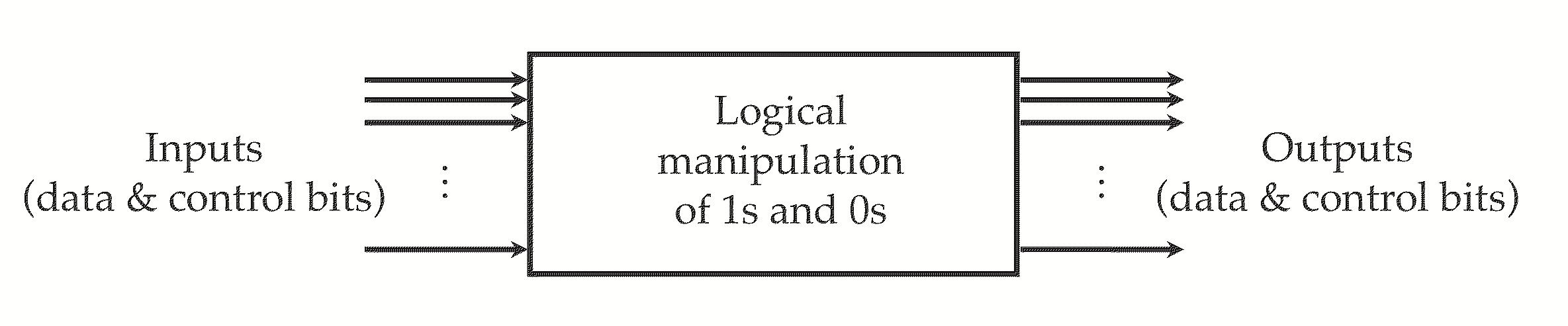
Block with several input and output lines
In VHDL, the external description of a system, showing its input and output ports, is called an entity. A port may represent a single bit, or a bundle of bits (bit vector, or bus). Consider, for example, the four-bit up-down counter depicted in Figure 5.2.2. There are two single-bit input ports, CLK and UP/DOWN, a single-digit seven-segment output bus, and a single-bit output port for the terminal count signal (TC).

Block with clock and up/down inputs, seven-segment and terminal count outputs.
A VHDL model for the counter begins with the entity block in Listing 5.2.3. Each port is declared with a name, a direction (in or out), a data type (always “std_logic” for single bits or “std_logic_vector” for bundles of bits), and an optional (but always advisable) comment. The notation may seem cumbersome at first, but so did your first programming language, and in time, you mastered its rules. The good news is that all entity blocks are structured like this. There are almost no additional features to learn.
entity counter4_updown is
	port(clk:       in  std_logic;                -- clock
	     updown:    in  std_logic;                -- 0 for up, 1 for down
	     segments:  out std_logic_vector(0 to 6); -- segments a-g
	     TC:        out std_logic );              -- terminal count
end counter4_updown;
The declaration
std_logic_vector(0 to 6) for segments merits an additional comment. This is a vector of seven bits, indexed from left to right. segments(0) corresponds to segment a, segments(1) is segment b, up to segments(6), which is segment g. This is one way to index a bit vector in VHDL. The other way, used when the vector must be indexed with its most significant bit at the left end, is, e.g., std_logic_vector(7 downto 0) for an eight-bit byte. The downto form is always used for numbers.
Checkpoint 5.2.4.
Checkpoint 5.2.5.
Write an entity block for the odd number detector, Checkpoint 1.3.3. Write the entity so that the input has eight bits rather than two.
Answer.
entity odd_number is
   port(x:   in  std_logic_vector(7 downto 0); -- 8-bit input
        y:   out std_logic );                -- 0 if even, 1 if odd
end odd_number;
Checkpoint 5.2.6.
Write an entity block for the “\(x \gt y\)” function. Write the entity so that the inputs have four bits rather than two.
Answer.
entity x_gt_y is
   port(x:   in  std_logic_vector(3 downto 0); -- 4-bit input
        y:   in  std_logic_vector(3 downto 0); -- 4-bit input
        g:   out std_logic );                  -- 1 if x > y, 0 otherwise
end x_gt_y;
Exercises Exercises
1. VHDL models.
For additional practice, write entity blocks for the earlier example systems:
- Multiplexer, Checkpoint 1.3.6.
- One-hot decoder, Figure 1.3.2.
- Priority encoder, Checkpoint 1.3.7.

