The simplest counter is just a register and an incrementer. On each rising clock edge, the count advances, and when it reaches the capacity of the register (\(2^N-1\) for an \(N\)-bit counter), on the next edge the count resets (or “rolls over”) naturally to zero. Control inputs modify this natural sequence, e.g., by halting the count (enable) or forcing it to zero (clear). In this course, all counter controls are designed to be synchronous, acting on the rising clock edge. They are never asynchronous.
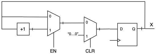
When there is more than one control input, the designer must decide how to prioritize them. Typically, the clear function has the highest priority, followed by the enable. These functions are often built into the register itself. In hardware, the priority of control signals is expressed through a sequence of multiplexers, with the highest priority control placed closest to the register Figure 10.2.1
Block diagram
Figure10.2.1.Counter with synchronous clear (CLR) and enable (EN) controls. CLR is given priority over EN by placing it closer to the register.
The clear-over-enable priority is modeled in VHDL by nested if-then-else statements.
-- Signal X is previously declared as unsigned; all other signals are std_logic

   process(clk)
   begin
      if rising_edge(clk) then
         if CLR = '1' then                -- 1
            X <= (others => '0');         -- 2
         elsif EN = '1' then              -- 3
            X <= X+1;
         end if;
      end if;                             -- 4
   end process;
Listing10.2.2.VHDL model for the counter in Figure 10.2.1. Comments are keyed to notes in the text.
The important features of this model (compare to the logic diagram, Figure 10.2.1) are:
By testing CLR first, it is given priority over EN. The first decision to be made is whether we will clear the counter.
The VHDL construction (others => '0') conveniently makes a vector "0...0" whose length matches to size of X.
If CLR is not asserted, EN is tested and if it is TRUE, the counter is incremented.
If neither CLR nor EN is asserted, no action is taken, and X is unchanged. There will be no latch warning (Section 13.3) because the process is clocked; we intend for a register to be synthesized.
Watch the following video for more about nested control statements.
ExercisesExercises
1.Up-down counter with terminal count output.
Modify the counter in Figure 9.2.2 to have a single control input, UPDOWN, and to assert the TC signal on \(M-1\) when counting up, and 0 when counting down. Draw a block diagram, and then write a VHDL model (see Listing 9.2.3). Validate the model with a testbench and simulation.
2.Preloadable counter.
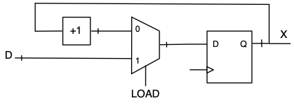
Design a counter with a single control input, LOAD, and a (vector) data input, D. When LOAD is asserted, the data at D is synchronously loaded into the counter’s register, overriding the current count value. When LOAD=0, the counter counts normally. Draw a block diagram and write a VHDL model based on the block diagram.
Answer.
Block diagram:
Block diagram
Figure10.2.3.Counter with parallel preload inputs.
VHDL model:
-- Signals X and D are previously declared as unsigned;
-- all other signals are std_logic.

   process(clk)
   begin
      if rising_edge(clk) then
         if LOAD = '1' then
            X <= D;
         else
            X <= X+1;
         end if;
      end if;
   end process;
Listing10.2.4.VHDL model for the counter with parallel preload inputs.
3.Countdown timer.
Design a counter with a single control input, LOAD, a (vector) data input, D, and a terminal count signal, TC. When LOAD is asserted, the data at D is synchronously loaded into the counter’s register. When LOAD=0, the counter counts normally, down to zero. When zero is reached, TC is asserted and the counter holds at zero until LOAD is asserted again. Draw a block diagram and write a VHDL model based on the block diagram.