This section focuses on an all-too-common mistake, when a designer writes an if-then statement and neglects to include the else clause. Here is a simple example:
process(a, x)       -- 1
begin
   if a='1' then    -- 2
      y <= x;       -- 3
   end if;
end process;        -- 4
Listing13.3.1.A VHDL model with an incomplete if-then-else construction. Comments are keyed to notes in the text.
Let’s trace its function step-by-step, assuming an initial event on x:
The event on x, a change from ’0’ to ’1’ or from ’1’ to ’0’, activates the process.
The value of a is tested.
If a is ’1’, this statement is evaluated, and y is scheduled to be assigned the value of x when the process suspends. Otherwise, this statement is skipped.
The process suspends, and y is either assigned the value of x, or, because there is no else clause, y is unchanged (implicitly, y <= y).
Note that as long as a is ’1’, y will follow any changes in x, but if a changes to ’0’, the value of yholds at whatever its last assignment was. This property of VHDL is called implied memory. The model behaves somewhat like a flip-flop, but without an edge trigger. It is called a latch, D latch, or transparent latch. We can write the model in a standard form by renaming the signals.
latch: process(EN, D)
begin
   if EN='1' then    -- While the latch is enabled,
      Q <= D;        -- the output follows the input
   end if;
end process latch;
Listing13.3.2.VHDL model for a transparent latch.
The control input is called EN, “enable”. While the latch is enabled (EN is ’1’), it is transparent, in that the data input, D, passes right through to the output, Q. When the latch is disabled (EN is ’0’) the latch holds its value.
Checkpoint13.3.3.
Write a truth table for the transparent latch, with inputs EN and D, and output Q.
Answer.
EN
D
Q
0
—
Q (hold)
1
0
0
1
1
1
Prior to the invention of edge-triggered flip-flops, latches were used for bit storage. In hardware, a transparent latch requires about half the transistors of an edge-triggered flip-flop. However, edge-triggered flip-flops are easier to design with, and we use then exclusively in this course. The presence of a latch in a design is an error to be avoided.
While you will not intentionally use a latch in a design, they will sneak in if you are not careful when you write if-then-else and case statements, and very often the unexpected presence of a latch in a design will show up as a bug in physical test.
Latches are avoided by remembering always to cover all the alternatives in a decision:
Make sure all your if-then statements include an else clause. The exception is a clocked process (if rising_edge(clk) then...end if), where you intend to have (edge-triggered) storage.
Make sure your case statements cover all their alternatives. The easiest way to do this is to include when others => ... as the last statement in the case. You may either write when others => null; which causes no action to be taken, or put in a default action, like when others => y <= '0';.
As with combinational loops, an incomplete if-then statement is not a violation of the language, and will not throw an error. However, the synthesis tool will give you a warning stating that a latch has been synthesized for a signal. Make it a habit to always check your synthesis warnings. If a latch warning turns up for some signal, go back through your code and find where the signal is assigned. Figure out why a latch is being synthesized (depending on how complex your code is, it might not be immediately obvious), and correct the problem before proceeding. It is much easier to fix at this stage than to discover it at physical test.
Example13.3.4.Incomplete if-then, simulated.
Here is the full VHDL model for an incomplete if-then statement, written like a multiplexer.
library IEEE;
use IEEE.STD_LOGIC_1164.ALL;

entity latch_mux is
    Port ( sel : in STD_LOGIC;
           x : in STD_LOGIC;
           y : out STD_LOGIC);
end latch_mux;

architecture Behavioral of latch_mux is
begin

mux: process(sel, x)
begin
    if sel='1' then
        y <= x;
    end if;
end process mux;

end Behavioral;
And here is a testbench to exercise its functionality:
library IEEE;
use IEEE.STD_LOGIC_1164.ALL;

entity latch_mux_tb is
end latch_mux_tb;

architecture Behavioral of latch_mux_tb is

component latch_mux is
    Port ( sel : in STD_LOGIC;
           x : in STD_LOGIC;
           y : out STD_LOGIC);
end component;

signal sel, x: std_logic := '0';
signal y: std_logic := '0';
constant T: time := 100ns;

begin

dut: latch_mux port map(
    sel => sel,
    x => x,
    y => y );

stim_proc: process
begin
    sel <= '1';
    x <= '0';   wait for T;
    x <= '1';   wait for T;

    sel <= '0';
    x <= '0';   wait for T;
    x <= '1';   wait for T;

    sel <= '1'; x <= '0'; wait for T;
    sel <= '0'; x <= '0'; wait for T;
                x <= '1'; wait for T;
    sel <= '1'; x <= '1'; wait for T;
    sel <= '0'; x <= '0'; wait for T;
                x <= '1'; wait for T;
    wait;
end process stim_proc;

end Behavioral;
Running this simulation with the Xilinx Vivado tool resulted in the following waveform. Observe that the system is transparent from x to y when sel is ’1’, and latched when sel is ’0’.
Timing diagram from simulation
Figure13.3.5.Vivado simulation of the incomplete if-then model. Observe the transparent latch action when SEL is alternately ’1’ and ’0’.
Example13.3.6.Incomplete if-then, synthesized.
The VHDL model in Example 13.3.4 was synthesized in Vivado. The following warning was generated:
Image of a Vivado latch warning
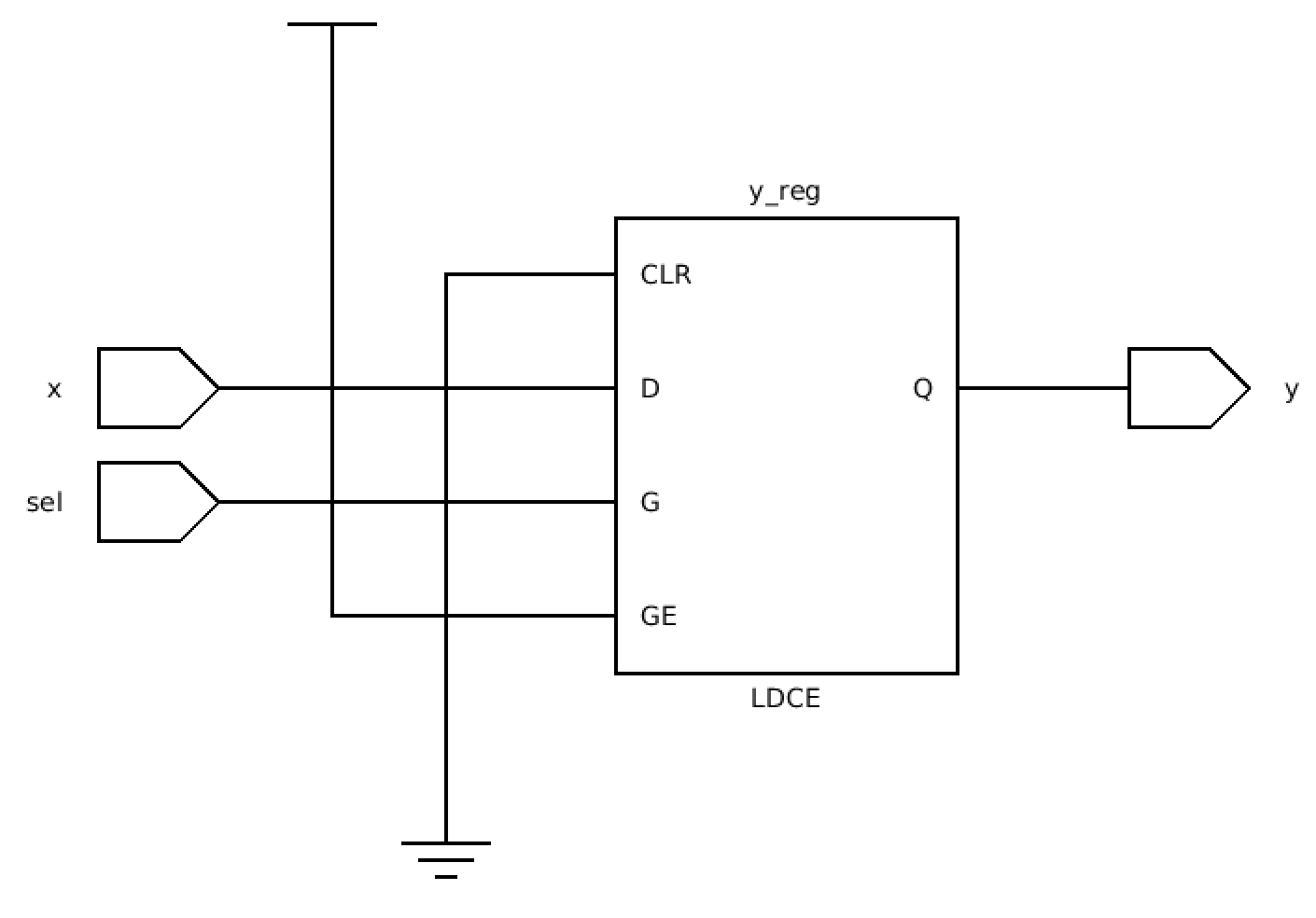
The warning explains that a latch, denoted y_reg, was “inferred” by the synthesis tool from the VHDL model at line 46, which is the if-then statement. The schematic of the synthesized design reveals the same:
Image of a Vivado latch warning
A latch element (LDCE) is synthesized, with SEL connected to the enable (G) input, X connected to the data (D) input, and Y connected to the output (Q). The additional inputs, CLR and GE, are explained in the Vivado documentation [21].