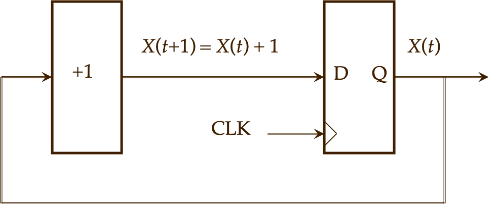
A counter is a register combined with an incrementer, Figure 8.3.1.
Figure8.3.1.A counter consists of a register to hold the current state, and an incrementer to calculate the next state.
We can model this in VHDL with a register and logic equations for the incrementer. Using previously derived equations, the model for a two-bit binary counter can be written like this, with two concurrent processes:
-- D and X are previously declared std_logic_vector(1 downto 0)

reg: process(clk)                -- State update (clocked)
begin
   if rising_edge(clk) then
	     X <= D;
      end if;
   end if;
end process reg;

incr: process(X)                 -- Next state (asynchronous)
begin
   D(0) <= not(X(0));
   D(1) <= X(1) xor X(0);
end process incr;
Listing8.3.2.VHDL model for a two-bit binary counter.
This model clearly separates the register that stores the counter’s state from the incrementer logic. The reg process updates on every rising clock edge. The update to X causes an event that activates the incr process, which computes new inputs for the register. This matches the behavior of the block diagram, Figure 8.3.1.
While it is often advantageous to separate the state register and the next state logic in this way, for something as simple as a counter it is needlessly complicated. We can accomplish the same thing, without any loss of clarity, with one process:
-- X is previously declared std_logic_vector(1 downto 0)

ctr2: process(clk)
begin
   if rising_edge(clk) then
      X(0) <= not(X(0));
      X(1) <= X(1) xor X(0);
   end if;
end process ctr2;
Listing8.3.3.VHDL model for a two-bit binary counter, written with one synchronous process.
A rising clock edge activates the process and causes the two expressions for X to be evaluated. The new value of X(0) is scheduled to be the inverse of the current value of X(0). The new value of X(1) is scheduled to be the exclusive-OR of the two current values of X(0) and X(1). At the end of the process, the two X bits are simultaneously updated to their new values and execution suspends, pending the next clock event.
This is a more compact expression for the counter, but it is not easily extended to more than two bits. We would need a new logic equation for each additional bit, and successive equations would be more complex, depending on all the less-significant bits.
VHDL provides numeric data types with arithmetic operations defined. Here is how the same counter is written, using these capabilities.
library ieee;
use ieee.std_logic_1164.all;
use ieee.numeric_std.all;                           -- 1

entity counter2 is
   port( clk:    in  std_logic;
         X:      out std_logic_vector(1 downto 0) );
end counter2;

architecture behavior of counter2 is
   signal uX:    unsigned(1 downto 0);             -- 2

begin
ctr2: process(clk)
   begin
      if rising_edge(clk) then
        uX <= uX + 1;                              -- 3
      end if;
   end process ctr2;

   X <= std_logic_vector(uX);                      -- 4
end behavior;
Listing8.3.4.VHDL model for a two-bit binary counter, using arithmetic operations. Comments are keyed to the explanation in the text.
Here are the important new VHDL features in this model:
The additional library, ieee.numeric_std [6], [1], pp 298ff, and [15], supplies the arithmetic data types and operations for unsigned (nonnegative) and signed (positive and negative) arithmetic. We need the numeric_std library because the std_logic_vector type does not support arithmetic.
The counter’s state is held by a signal of type unsigned.
The state update is a simple arithmetic operation. The numeral 1 is an integer, and by the VHDL rules of unsigned arithmetic, an integer may be added to an unsigned number. Without this, the expression would be written uX <= uX + "01", explicitly writing the increment as a two-bit binary number. The two-bit addition is modulo-4: 3 + 1 = 0.
By convention, all entity ports in a VHDL model must be std_logic or std_logic_vector. This line a type cast, converting the internal unsigned count to std_logic_vector type.
The biggest advantage of this version of the counter is that it easily extends to larger numbers by simply increasing the lengths of X and uX.
ExercisesExercises
1.Counter with two controls.
Modify the counter in Listing 8.3.4 to have eight bits, with synchronous reset and enable. As usual, reset has priority over enable.
2.Up-down counter.
Modify the counter in Listing 8.3.4 to be an eight-bit up-down counter. When control input UPDOWN is ’0’, the counter counts up, and when it is ’1’, the counter counts down. Counting up, 255 wraps around to 0, and counting down, 0 wraps around to 255.