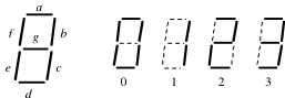
A popular way to display numerals uses seven LED-illuminated segments, arranged as shown in Figure 16.1.1. The segments are labeled \(a\) through \(g\text{.}\) The display can easily show the decimal numerals 0 through 9, and with a little imagination, the additional hexadecimal characters A through F (as A, b, c, d, E, F). A display may also include a decimal point as an eighth "segment".
Figure16.1.1.A single-digit seven-segment display can show 0-9 and A-F (as A, b, c, d, E, F).
The signals to drive the segments are produced by a special 4-to-7 decoder that follows the truth table shown in Figure 16.1.2.
\(\mathbf{x}\)
\((x_3 \ x_2 \ x_1 \ x_0)\)
\((a \ b \ c \ d \ e \ f \ g)\)
\(\mathbf{x}\)
\((x_3 \ x_2 \ x_1 \ x_0)\)
\((a \ b \ c \ d \ e \ f \ g)\)
\(0\)
\(0 \ 0 \ 0 \ 0\)
\(1 \ 1 \ 1 \ 1 \ 1 \ 1 \ 0\)
\(8\)
\(1 \ 0 \ 0 \ 0\)
\(1 \ 1 \ 1 \ 1 \ 1 \ 1 \ 1\)
\(1\)
\(0 \ 0 \ 0 \ 1\)
\(0 \ 1 \ 1 \ 0 \ 0 \ 0 \ 0\)
\(9\)
\(1 \ 0 \ 0 \ 1\)
\(1 \ 1 \ 1 \ 0 \ 0 \ 1 \ 1\)
\(2\)
\(0 \ 0 \ 1 \ 0\)
\(1 \ 1 \ 0 \ 1 \ 1 \ 0 \ 1\)
\(10 (A)\)
\(1 \ 0 \ 1 \ 0\)
\(1 \ 1 \ 1 \ 0 \ 1 \ 1 \ 1\)
\(3\)
\(0 \ 0 \ 1 \ 1\)
\(1 \ 1 \ 1 \ 1 \ 0 \ 0 \ 1\)
\(11 (b)\)
\(1 \ 0 \ 1 \ 1\)
\(0 \ 0 \ 1 \ 1 \ 1 \ 1 \ 1\)
\(4\)
\(0 \ 1 \ 0 \ 0\)
\(0 \ 1 \ 1 \ 0 \ 0 \ 1 \ 1\)
\(12 (C)\)
\(1 \ 1 \ 0 \ 0\)
\(1 \ 0 \ 0 \ 1 \ 1 \ 1 \ 0\)
\(5\)
\(0 \ 1 \ 0 \ 1\)
\(1 \ 0 \ 1 \ 1 \ 0 \ 1 \ 1\)
\(13 (d)\)
\(1 \ 1 \ 0 \ 1\)
\(0 \ 1 \ 1 \ 1 \ 1 \ 0 \ 1\)
\(6\)
\(0 \ 1 \ 1 \ 0\)
\(0 \ 0 \ 1 \ 1 \ 1 \ 1 \ 1\)
\(14 (E)\)
\(1 \ 1 \ 1 \ 0\)
\(1 \ 0 \ 0 \ 1 \ 1 \ 1 \ 1\)
\(7\)
\(0 \ 1 \ 1 \ 1\)
\(1 \ 1 \ 1 \ 0 \ 0 \ 0 \ 0\)
\(15 (F)\)
\(1 \ 1 \ 1 \ 1\)
\(1 \ 0 \ 0 \ 0 \ 1 \ 1 \ 1\)
Figure16.1.2.Truth table for hexadecimal to seven-segment decoder. A TRUE (1) output, \(a - g\text{,}\) activates the respective segment.
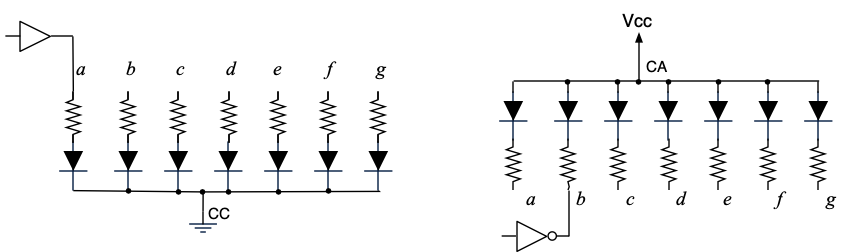
Inside the display, the LEDs are wired in one of two ways. In a common-cathode display, the cathodes are wired together. There is a single common cathode connection for all the segments, and they have separate anode connections. The cathode terminal is wired to ground, and a segment is turned on by driving its anode HIGH, through a current-limiting resistor, sourcing current through the LED. In a common-anode display, on the other hand, the anodes are wired together and the segments have separate cathode connections. The anode terminal is wired to Vcc, and a segment is turned on by driving its cathode LOW through a current-limiting resistor, sinking current from Vcc through the LED (Figure 16.1.3).
For a common-cathode display, the segment signals \(a - g\) in the truth table, Figure 16.1.2, drive the anodes with a high true voltage convention, meaning that a logical TRUE (1) is represented electrically by a HIGH voltage. For a common-anode display, the cathodes must be driven low to activate the segments. The same truth table applies, but the segment signals are low true, meaning that a logical TRUE (1) is represented electrically by a LOW voltage. Rather than rewrite the truth table swapping 1s and 0s, it is preferred to use the same truth table and just run \(a - g\) through NOT gates to the cathodes. In this way, ’1’ and ’0’ still mean TRUE and FALSE, and the inverter is interpreted as changing the sense of the signal from high true to low true.
Often, the current requirements of the LEDs, particularly the common connections, exceed the source/sink capacity of a logic circuit, and additional buffers or transistor switches with higher current capability are used between the logic and display.
Figure16.1.3.(Left) A common-cathode seven-segment display. Segment \(a\) is shown being activated by driving its anode HIGH through a current-limiting resistor. (Right) A common-anode seven-segment display. Segment \(b\) is shown being activated by driving its cathode LOW, through a current-limiting resistor.
Checkpoint16.1.4.
Why should each segment have its own current-limiting resistor --- why not wire one current-limiting resistor between the common terminal and Vcc or ground?
Hint.
How much current can flow through the current-limiting resistor (Ohm’s Law)? What will you see if this current is divided among all the active LEDs?
Checkpoint16.1.5.
Write a VHDL process, using a case statement, that models the seven-segment decoder’s truth table.