
Section 13.5 Incomplete sensitivity lists
The simple rules for remembering what signals/ports to put in a process sensitivity list are (Section 9.3)
- For clocked logic, the clock signal must be on the sensitivity list. Any inputs inside
if rising_edge(clk) ... end if;may be omitted from the sensitivity list. - For unclocked (combinational) logic, all inputs must be on the sensitivity list.
Though these rules are simple, they are often neglected. What can go wrong as a result?
Simulation.
To illustrate what can happen, consider a very simple process:
-- a, b, y are declared std_logic
process(a,b)
begin
  y <= a and b;
end process;
This process was simulated three times: with both
a and b on the sensitivity list, with aalone, and with b alone. The results are displayed in Figure 13.5.1, below.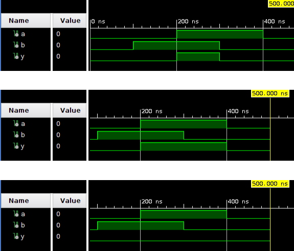
Simulation waveforms
In the first case, the waveforms show
y is ’1’ only when a and b are ’1’, as expected. In the second case, when input b changes from ’1’ to ’0’ at 300ns, the output remains high. Since the process is insensitive to b, it does not activate on this event and the output holds at its previous value, which was set at 200ns when a changed from ’0’ to ’1’. In the third case, because the process is insensitive to a and the output does not change to ’1’ at 200ns. The output is always 0.Leaving inputs off the sensitivity list causes incorrect and misleading simulation results.
Synthesis.
Continuing with the AND gate toy problem, the Vivado synthesis tool detects the missing input on the sensitivity list and throws a warning.

Synthesis warning message, “signal ’a’ is read in the process but is not in the sensitivity list”
However, Vivado’s synthesis tool assumes that the omission was accidental, and adds missing signals to the sensitivity list ([20], p.195). Consequently, for the AND gate example, all three cases synthesize to the same logic, Figure 13.5.2.
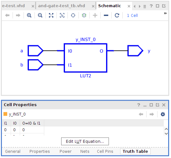
Vivado synthesis schematic, and LUT truth table.
This is the behavior of the Vivado tool. Other synthesis tools may respond differently, so always be careful to read the synthesis warnings and correct any incomplete sensitivity lists. Omissions will, at the least, result in incorrect simulations, and could result in incorrect logic as well.

