In an earlier exercise, Checkpoint 1.3.6, you were introduced to the two-input multiplexer, which has two one-bit data inputs, \((A, B)\text{,}\) a control bit \(S\) (“select”), and a one-bit output, \(y\text{.}\) The control bit \(S\) selects whether \(y=A\) or \(y=B\text{.}\) The function of the multiplexer is described by the following if-then-else:
        if S=='0'
            then y=A;
            else y=B;
        end if;
which can be expressed as a logic equation,
\begin{equation*}
y = S'A + SB.
\end{equation*}
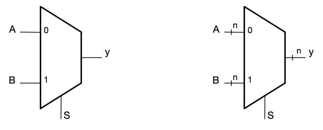
There are numerous applications of multiplexers in hardware design, as there are for "if-then-else" statements in software. So that the gate-level sum-of-products circuit doesn’t have to be drawn every time a designer wants to use a multiplexer, the component has its own logic symbol Figure 4.1.1.
Logic symbol
Figure4.1.1.Two-input (or "two-to-one") multiplexer symbol. (Left) Selecting one of two single-bit signals; (Right) Selecting one of two \(n\)-bit bundles.
The same symbol may be used to indicate that the choice is between single-bit or multi-bit signals, just by labeling the input and output lines with the number of bits.
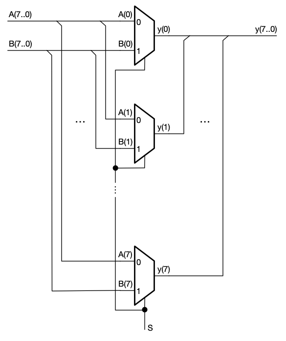
A multiplexer with \(n\)-bit inputs is constructed from \(n\) simple multiplexers as shown in Figure 4.1.2.
Figure4.1.2.An \(8\)-bit multiplexer is constructed from \(8\) simple multiplexers, with a common select bit. The inputs and output must have the same number of bits. The notation A(7..0) indicates an 8-bit bundle, with individual bits denoted A(0) through A(7). Each multiplexer selects between a pair of single inputs. A perpendicular junction between two wires, as on the select line, indicates a connection, as usual. An angled junction indicates a bus tap, where one or more wires branch out of a bundle, as shown on the multiplexer inputs, or merge into a bundle, as on the output.
The multi-bit multiplexer notation, Figure 4.1.1, packs a lot of logic into a compact symbol!
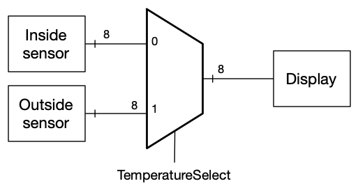
Any time you have the need to select between two alternatives, think "multiplexer". For example, suppose a temperature sensor outputs an 8-bit number. One such sensor is placed outside the window in your room, and the other sensor is on your desk. An 8-wire bundle runs from each sensor to a multiplexer, and you can select which temperature to read with a signal TemperatureSelect applied to the select bit, Figure 4.1.3.
Multiplexer with two temperature inputs and a display output.
Figure4.1.3.Using an 8-bit, two-input multiplexer to select which of two temperature sensors to display.
Checkpoint4.1.4.
Here is a selection process that frequently occurs in practice. The system has two control bits, G and S, two data inputs, A and B, and one data output, y. When G='0', the output is 0, regardless of the values of the inputs. When G='1', typical multiplexer behavior results, with A or B selected, depending on the value of S. Show, via a logic diagram, how to implement this with two two-input multiplexers.
Multi-input multiplexers.
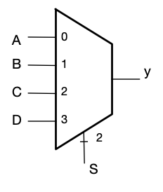
Multiplexers can also be devised that select among more than two input signals. A four-to-one multiplexer, Figure 4.1.5, selects one of four inputs. The inputs may be one or \(n\) bits each. To choose among four inputs requires two select bits, which together encode the numbers 0, 1, 2, 3 (binary "00", "01", "10", "11").
Four-input multiplexer
Figure4.1.5.A multiplexer with four inputs requires two select bits. The select bits may be drawn as a two-bit bundle, as shown here, or as two individual wires, whichever is more convenient for the designer.
A multi-input multiplexer functions like a "case" or "switch" statement in software:
        case S is
            when "00" => y <= A;
            when "01" => y <= B;
            when "10" => y <= C;
            when "11" => y <= D;
        end case;
Checkpoint4.1.6.
Write a truth table for a four-to-one multiplexer, with four one-bit inputs \(A\) through \(D\text{,}\) output \(y\text{,}\) and two select bits \(S_0\) and \(S_1\text{.}\) The truth table can be simply written with three columns, for the two select bits and the output. Also write a logic equation, \(y = f(A, B, C, D)\text{.}\)
Answer.
\(S_1\)
\(S_0\)
\(y\)
0
0
A
0
1
B
1
0
C
1
1
D
The logic equation is \(y = S_1^\prime S_0^\prime A + S_1^\prime S_0 B + S_1 S_0^\prime C + S_1 S_0 D\text{.}\)
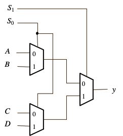
The logic equation may be factored into a combination of three two-to-one multiplexers, like this:
\begin{equation*}
y = S_1^\prime (S_0^\prime A + S_0 B) + S_1 (S_0^\prime C + S_0 D).
\end{equation*}
This form is of practical interest because of a special two-input multiplexer circuit that requires only six CMOS transistors, making an implementation based on this form quite small and fast. Learn about it in this video:
Checkpoint4.1.7.
Draw a logic diagram for the four-input multiplexer using three two-input multiplexers.
Answer.
Four-input multiplexer from two-input multiplexers
Checkpoint4.1.8.
Calculate and compare the number of transistors required for (a) the "case-like" four-input multiplexer made with NAND and NOT gates, (b) the four-input multiplexer constructed from two-input multiplexers with NAND and NOT gates, and (3) the four-input multiplexer constructed from six-transistor two-input multiplexers.
A multiplexer that selects one of four multi-bit bundles is made by connecting single-bit multiplexers together, similarly to Figure 4.1.2. Even larger (e.g., 8-to-1, 16-to-1) multiplexers (with three and four select bits, respectively), may also be compactly constructed from two-input CMOS multiplexers. The circuits have more than two layers of logic, and consequently are slower direct than sum-of-products circuits, but they are much smaller and use less power.