
Work through the multiplexer model again, with an event on the select bit. What potential problem(s) do you see?
Section 6.1 Events
The architecture for the simple two-input multiplexer model, Listing 5.3.1, consists of a single statement,
y <= (not(S) and A) or (S and B);. We begin this chapter by unpacking how this statement models the multiplexer hardware. The multiplexer has three input ports, \(A, B, S\text{,}\) and one output port, \(y\text{.}\) While the inputs are steady, 1 or 0, the output is steady, 1 or 0. The output only changes in response to a change on one of the inputs. Such a change, from 0 to 1 or from 1 to 0, is called an event. An event causes transistors in the circuit to switch on or off in response to the new input values, which result in a new output value in accordance with the logic of the circuit. Between events the circuit is in steady state.One of the uses of a VHDL model is to test the logical function of a design. A software tool called a simulator creates a sequence of input events and computes outputs according to the statements in the VHDL model. The results may then be examined to see if they agree with the expected behavior of the system. Just as in a real circuit, a statement in a VHDL model, e.g.,
y <= (not(S) and A) or (S and B);, is normally inactive, waiting for an event on one or more of the inputs \(A, B\) and \(S\text{.}\) In response to an event, the simulator executes the statement and assigns a new value of \(y\) appropriately. After this, execution is suspended until the next event.This starts to get interesting when more than one statement is involved. Consider the other multiplexer model, Listing 5.3.4, which has three statements:
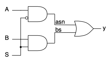
Logic diagram.
asn <= not(S) and A;   -- 1
bs <= S and B;         -- 2
y <= asn or bs;        -- 3
Suppose, in response to earlier events, \(A=0, B=1, S=0\text{,}\) so \(y=A=0\text{.}\) The circuit is in steady state and all three statements in the model are suspended. Now, let \(A\) change from 0 to 1. This event activates the upper AND gate, and its output changes from 0 to 1. This makes an event on the input of the OR gate, and it activates, changing its output from 0 to 1. The lower AND gate is unaffected and remains inactive.
An analogous chain of events occurs in the execution of the VHDL model. The event on port
A activates Statement 1, and it is evaluated. The value of the signal asn is changed, then the statement suspends, pending a new event. The change in asn is an event which activates Statement 3. The statement is evaluated and a new value is assigned to the port y. Then the statement suspends pending a new event. There are no events on ports S or B, so Statement 2 remains suspended. If a new event occurs, on B, say, execution of the model will resume with activation and evaluation of Statement 2, which causes an event on signal bs, activating Statement 3. Statement 1 will remain inactive, because it does not depend on B or bs. Note how the VHDL exactly mimics the operation of the circuit.Suppose we reorder the statements, like this:
Logic diagram.
y <= asn or bs;        -- 3
asn <= not(S) and A;   -- 1
bs <= S and B;         -- 2
If we set up the same initial conditions as before, \(A=0, B=1, S=0\text{,}\) and \(y=A=0\text{,}\) and repeat the same sequence of events, the statements will be executed identically: Statement 1, then 3, then 2, then 3. The execution of the statements in the model depends not on the order in which they are written, but on the sequence of events. For this reason, VHDL is said to be an event-driven language.
A circuit operates, processing its inputs and generating outputs, as long as power is applied. A VHDL simulator processes events, in an implicit “do forever” loop, until its execution is terminated.

