
Section 12.1 State machines
Structurally, a state machine is very much like a counter: a register to hold the current state and combinational logic to determine the next state, based on the current state and any external inputs. Additionally, there may be combinational logic to assert outputs in particular states, such as the terminal count signal from a counter.
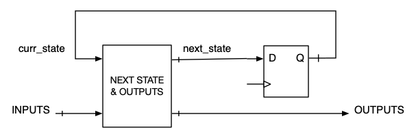
Block diagram
In a counter, the bits of the state register represent a binary number, and the next state logic increments or decrements the value of the number, or modifies the count sequence based on the inputs. The “state” of a state machine is more general than a numerical count, and the next state logic allows, in principle, for any state to be reached from any other state.
A state diagram is a graphical representation of the sequence of states that enables the designer to step away from the details of the logic and think at a higher level.
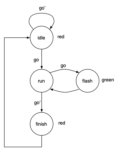
State diagram
In a classical design, each state is assigned a binary code, e.g., idle="00", run="01", flash="11", finish="10". Then, a truth table is derived with the current state and inputs on one side and the next state and the outputs on the other. This truth table is reduced to logic equations for the combinational logic, and the state machine is implemented with gates and flip-flops.
With VHDL, we go directly from the state diagram to a VHDL model, followed by simulation, synthesis, implementation, and physical test.

