We have seen that a VGA image, for our purposes, is a 640 (columns) \(\times\) 480 (rows) array of one- to twelve-bit pixels, updating at 60 frames per second. All that data must be communicated from the source (in our case, the Artix 7 FPGA on the Basys 3 board) to a VGA-compatible monitor.
Originally (think old TV sets), the glass screen of a "picture tube" was coated with a phosphorescent material that lit up in response to excitation by a beam of electrons. As the electron beam was swept in a raster pattern, line-by-line from top to bottom, the image was "painted" on the phosphorescent screen (see this Wikipedia article 1
en.wikipedia.org/wiki/Cathode-ray_tube
for more information about this vintage technology). Color images required three electron beams and more complex three-phosphor coatings to make red, green, and blue. Three analog voltages controlled the intensities of the beams as they moved, to create different mixtures of the three colors at each pixel. Modern monitors use either light-emitting diodes or backlit liquid crystal shutters to create the pixels, and the raster scanning is accomplished by counters that address the pixels sequentially, from left to right and from top to bottom.
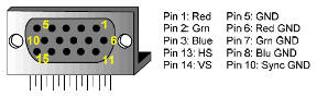
On the Basys 3, the values of red, green, and blue are each represented by a four-bit number. These are converted to analog voltages between 0 and 0.7 volts for compatibility with the monitor’s video inputs. In addition to the red, green, and blue video signals, two synchronization signals are required so that the counters in the monitor address the pixels in time with the sending of the data from the source. Horizontal sync pulses of a specified width produced by the source indicate the end of a single line, reset the horizontal counter and increment the vertical counter to the beginning of the next line. A vertical sync pulse of specified width at the end of a full frame resets the vertical counter back to the first line. A standard 15-pin connector brings these five video and sync signals from the source to the monitor, Figure 20.2.1
Figure20.2.1.DB-15 VGA connector [3]. The five signals are the Red, Green, and Blue pixel voltages, each with its own ground, and the horizontal (HS) and vertical (VS) sync pulses, which share a ground.
Checkpoint20.2.2.
What are the five signals required to display an image on a VGA monitor? Which are analog, which are digital?
Answer.
Red, green and blue video (analog); horizontal and vertical sync (digital).
For historical reasons (back to those analog video displays), there are blank pixels before and after a line of video, and blank lines above and below a frame of video. This has the effect of embedding the actual 640 \(\times\) 480 image in a larger 800 \(\times\) 525 field. Over sixty frames, this comes to \(800 \times 525 \times 60 = 25.2\) million pixels per second. It is more convenient for us to use a 25 MHz pixel clock, since it is simply one fourth of the 100 MHz Basys 3 master clock. For modern monitors, the slower clock works fine if the number of lines is reduced from 525 to 521 (\(800 \times 521 \times 60 = 25.008\) MHz).
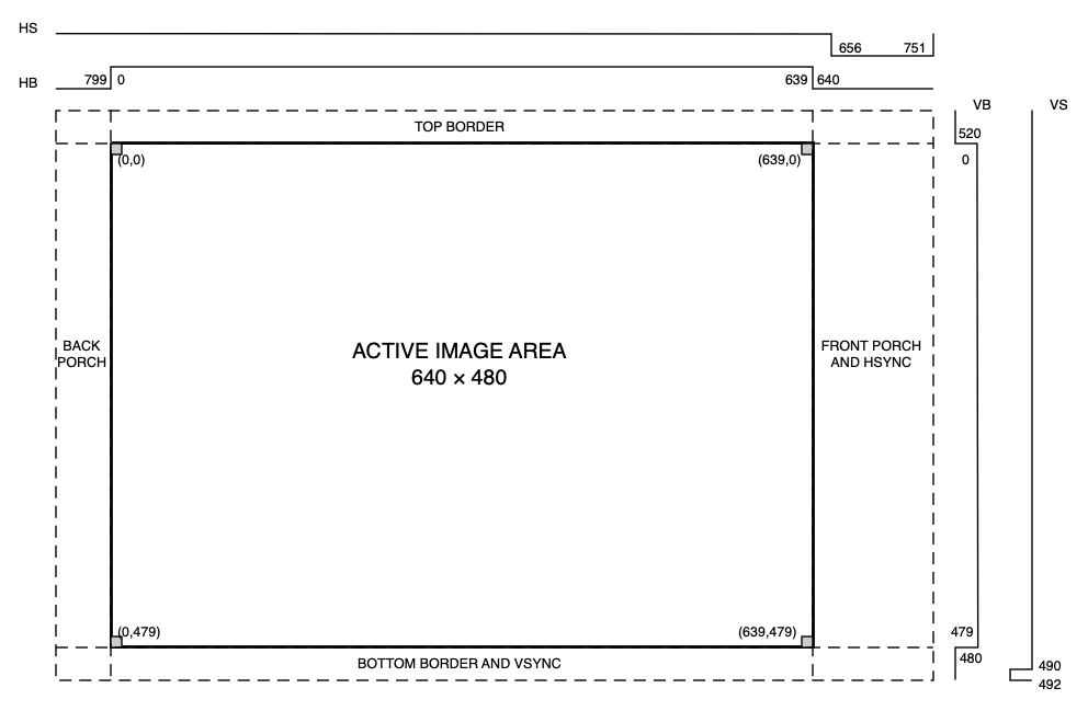
A timing diagram for the video signals is shown in Figure 20.2.3. Beginning at the left edge of the active area (column 0), there are 640 active pixels. The rest of the pixels, from 640 to 799, are blanked (zero), as indicated by the horizontal blanking (HB) waveform. The blanked region is divided into the "front porch", the horizontal sync pulse (HS), and the "back porch", which immediately precedes the start of the next active line. From the top of the active area (row 0), there are 480 active lines, followed by the vertical blanking region (lines of all zeros) from line 480 to line 520. Within this region are the bottom border, the vertical sync pulse, and the top border. The horizontal and vertical time scales are not the same. Although the vertical sync pulse appears quite thin in the drawing, just two lines, because each line consists of 800 pixels, it is actually quite long.
Figure20.2.3.Horizontal and vertical VGA timing. The horizontal time scale is in pixels. The vertical scale is in lines (one line is 800 pixels). HB and HS: Horizontal blanking, horizontal sync. VB and VS: Vertical blanking, vertical sync. Each pixel is one clock cycle at 25 MHz (40 ns). Each line is 800 pixels (32 \(\mu\)s).